Different Bracing Methods Are Permitted Within a Continuously Sheathed Braced Wall Line
Wall Bracing for Hurricane, High Wind, and Seismic Resistance
Scope
Construct the walls of a home with appropriately braced wall panels or shear walls to resist wind loads expected in the home's location.
- Reference the International Residential Code (IRC) tables to determine the amount of braced wall panels or shear wall needed based on the seismic and wind load of the home's location.
- Evaluate the braced wall panels or shear wall construction method(s) that will be used.
- Check building plans for adequate qualifying brace/shear wall for each floor, including the foundation walls in the basement and crawl space cripple walls.
- Install wood structural panels, metal strapping, or inset shear panels to increase the strength of the walls against shear forces.
- Install structural screws or metal straps to increase the uplift strength between the studs and the top and bottom plates.
See the Compliance Tab for related codes and standards requirements, and criteria to meet national programs such as DOE's Zero Energy Ready Home program, ENERGY STAR Certified Homes, and EPA Indoor airPLUS.
Description
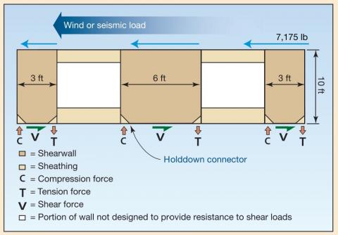
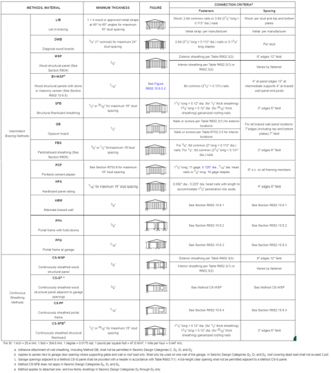
Walls need be braced such that they are able to withstand the extreme lateral loads imposed by events such as hurricanes, high winds, tornados, and seismic events without failing and causing loss of life (Figure 1). Wall bracing keeps rectangular walls straight when subjected to large lateral loads. This guide will focus on wood-framed homes in seismic design categories D0, D1, D2 and where the design wind speed is 115 mph or greater. This guide is intended to be a supplemental guide to the International Residential Code (IRC) Section 602.10. In all instances where there are discrepancies between this guide and IRC Section 602.10, the requirements stated in IRC Section 602.10 will take precedence. The IRC braced wall guidelines provide builders with almost as many options as the physics and materials to maintain adequate bracing will allow (see IRC Table R602.10.4 (IRC 2021) shown in Figure 2 below). However, some bracing methods have suboptimal implications with regard to common insulation and air sealing details, which will be discussed further below.
Location, Location, Location
The first step is to know what the ultimate wind speed and seismic design category are for the location of the home. Your local building code jurisdiction will have zoomed-in versions of the national wind maps presented in IRC Figure R301.2(4)A and R301.2(4)B and the national seismic map in IRC Figure 301.2(2). Alternatively, you can find the ultimate wind speed for your address of interest by entering it in the online ASCE 7 Hazard Tool. Be sure to select the correct ASCE 7 version that matches the ASCE 7 version used in the IRC adopted by your local building codes jurisdiction. The seismic design category of your building address can also be found using the Seismic Design Map Tool by the Structural Engineers Association of California; note this tool works nationally, not just in California. The 2018 and newer IRC uses ASCE/SEI 7-16 whereas the 2015 version of the IRC uses ASCE/SEI 7-10.
Choosing Your Bracing Method
The IRC details 16 different wall bracing methods as shown in Figure 2 (IRC Table R602.10.4). Five of these methods are specific to the areas around a large garage-like opening This still leaves eleven different wall bracing methods for builders to choose from.
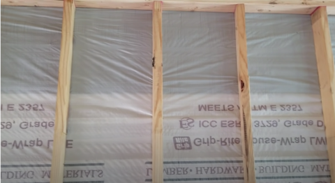
When deciding which wall bracing method to use, the options are narrowed by the seismic and wind loads the home is at risk of experiencing and the features of the home's design. Cost, durability, and energy efficiency are other drivers in the decision-making process. For example, if your house is in a low seismic risk zone (A, B, C), and therefore you only have to brace the walls for wind load, you may be able to use the let-in-bracing (LIB) method which uses diagonal metal strapping for all brace wall lines except the garage door area. If this is the case, you could build a house with no exterior sheathing as shown in Figure 3. However, in a home built with no exterior sheathing, it would be very difficult to achieve the air tightness requirements of today's energy-efficiency code requirements with any insulation method other than spray foam.
Which Walls Do I Need to Brace and Where Do I Need to Brace?
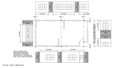
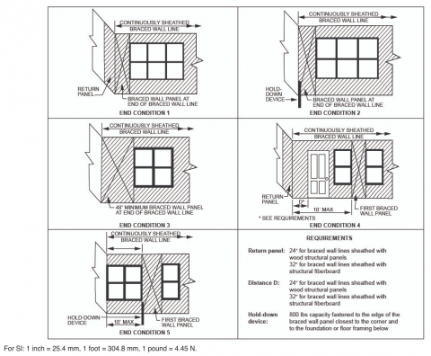
In addition to choosing the bracing method, you need to determine which walls need to be braced. If you are using a continuous sheathing method, the entire wall is braced by the sheathing. If you are not using a continuous sheathed bracing method, then you also need to know where on the wall to brace. The braced wall panel should begin within 10 ft of each end of a braced wall line as shown in Figure 4 (R602.10.2.2 in the IRC). A braced wall line (BWL) is an imaginary straight line through a building plan that represents the location of lateral resistance provided by the wall bracing. However, if the house is in seismic design categories, D0, D1, D2, then the braced wall panels must be located at each end of the braced wall line, unless the braced wall panel construction method is wood structural panel (WSP) or brick veneer wood structural panel (BV-WSP) with continuous sheathing (R602.10.2.2.1 in the IRC). If it is one of these two methods, then the braced wall panels are permitted to begin no more than 10 ft from each end of the braced wall line as long as each end of the braced wall line has one of these two options:
- At least a 24-inch-wide panel constructed using one of the following methods applied to each side of the building corner as shown in End Condition 4 of Figure 4: wood structural panel (WSP), continuously sheathed wood structural panel (CS-WSP), continuously sheathed wood structural panel adjacent to garage (CS-G), or continuously sheathed portal frame (CS-PF).
- The end of each braced wall panel closest to the end of the braced wall line shall have an 1,800-lb hold-down device fastened to the stud at the edge of the braced wall panel closest to the corner to anchor it to the foundation or framing below as shown in End Condition 5 of Figure 5.
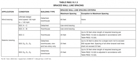
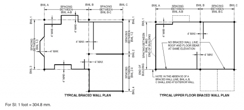
Besides the corner conditions, the distance between adjacent edges of braced wall panels along a braced wall line should not be greater than 20 ft as shown in Figure 4 (R602.10.2.2). Most homes are large enough that bracing just the exterior walls is not enough. This is especially true for homes located in seismic design categories D0, D1, and D2. The IRC specifies the maximum spacing between braced wall lines in Table R602.10.1.3, shown in Figure 5. As you can see, the bracing for homes in seismic design categories D0, D1, and D2, are required to be much more closely compared to homes that just have to be braced for high winds. Given these shorter maximum spacing allowances, in a typical home, one or more internal walls will often have to be a braced wall line as shown in Figures 4 and 7 where the dashed lines labeled BWL indicate the location of the braced wall line on the building plans.
How Much Braced Wall Length Do I Need?
The amount of qualifying braced wall length you need for each floor in each direction depends on the building shape, spacing distance between braced wall lines, and the wind and seismic loads of the home's location. The amount of qualifying braced wall length for a particular braced wall line is determined by selecting the greater of the wind and seismic braced wall length requirement as determined by the bracing requirements based on wind speed (see IRC Table R602.10.3(1)) and bracing requirements based on seismic design category (see IRC Table R602.10.3(3)). The wind-based braced wall length values in Table R602.10.3(1) are subject to the wind adjustment factors in Table R602.10.3(2) and the seismic design category-based braced wall length values are subject to the seismic adjustment factors in Table R602.10.3(4) in the IRC (ICC 2019). Walls offset by less than 4 feet of the braced wall line can be used to provide braced wall length to that braced wall line as shown in Figure 7. Note that the braced wall length requirements for wind speed Table R602.10.3(1) are determined by the furthest spacing or the average spacing between braced wall lines whereas in the seismic design category table, the braced wall length is based on the length of the braced wall line.
To clarify the braced wall line spacing for wind bracing, let's look at an example single-story house in Figure 8 (Verona 2009); refer to the link for a higher resolution image. An easy way to understand how to compute the braced wall line spacing is to use the "where's my help" method (Banjani 2016). For BWL A, we stand on the upper end of BWL A and look to the left to see if there is any bracing help, we find none, we look to the right and we find 15 ft of help. Then we look at the bottom end of BWL A and we do the same, on the left we find no help, but on the right, there is 25 ft of help. So, for BWL A we get an average braced wall line spacing of 20 ft:
No help + 15 ft
+ No help +25 ft
= 40 ft
Average: 40/2 = 20 ft
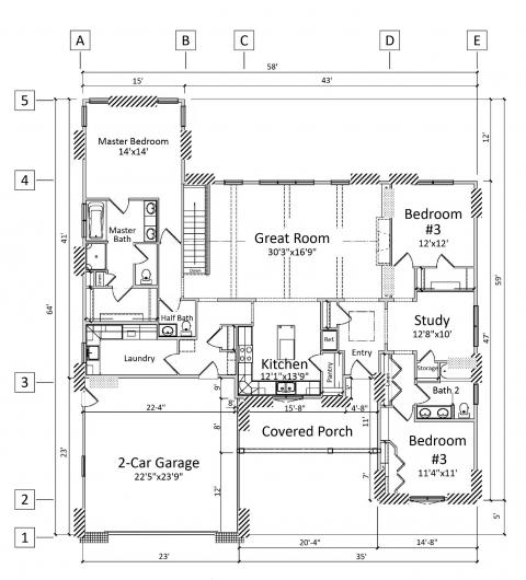
Let's assume the ultimate design wind speed for this location is 120 MPH. Looking at Table R602.10.3(1) we see that, for a single-story building with a braced wall line spacing of 20 ft, we would need 7 ft of braced wall panels along this braced wall line if we used the let-in bracing method. But that is not the correct answer. We still need to look at the wind adjustment factor table and apply any multipliers that are applicable. Right away, since there are five BWLs running in the direction of BWL A, we need to apply that multiplier of 1.6. Without applying any other wind adjustment factors from the table, the total length of braced wall panels needed along BWL A is 7 X 1.6 = 11.2 ft.
This process is repeated for the remaining braced wall lines and each floor starting from the cripple wall up to the top floor. If seismic loads need to be considered, measure the length of each braced wall line and measure and sum the length of the areas where a braced wall panel can be placed along that line. Refer to IRC Table R602.10.3(3), Table R602.10.3(4), and Table R602.10.5 to determine which areas along the braced wall line are sufficiently long to meet the minimum braced wall length requirement of your bracing method and how long of a braced wall can fit into that space. Sum up the lengths of braced wall panels to see if it is enough to meet the required amount. Many building codes divisions offer spreadsheets to help you summarize your findings such as the wind and seismic bracing calculators provided by the State of Oregon Building Codes Division. Note, many of these calculators don't replace requiring you to do calculations; they are merely aids.
What Qualifies as a Braced Wall Panel?
A braced wall panel must be a full-height section of wall that cannot have vertical or horizontal offsets. Therefore, the wall sections above and below a window or door cannot be counted as a braced wall panel that contributes to the required braced wall length. While the required braced wall length can be fulfilled using multiple braced wall panel sections, each one that contributes needs to have a certain minimum length, as specified in Table R602.10.5. This minimum length depends on the bracing method, wall height, and for some bracing methods, it also depends on the seismic design category and adjacent clear opening. For the DWB, WSP, SFB, PBS, PCP, and HPS bracing methods in seismic design categories A, B, and C ONLY, panels between 36 inches and 48 inches are allowed partial credit too as computed via Table R602.10.5.2 in the IRC. Additionally, there are requirements for where the first braced wall panel starts along a braced wall line; it must begin within 10 ft of each end of the BWL. For homes in seismic design categories D0, D1, D2 there are additional requirements for each end of a braced wall line as described in the section above, "Which Walls Do I Need to Brace and Where Do I Need to Brace?" Furthermore, the IRC section R602.10.2.3 specifies the minimum number of braced wall panels along a braced wall line. For BWLs shorter than 16 ft, two panels of any length or one panel that is 48 inches or more is required. For BWLs longer than 16 ft, two or more panels are required.
Mixing bracing methods is allowed along the same BWL. Typically, this is not done due to material logistics and constructability challenges such as maintaining a uniform plane for siding. If different bracing methods are employed, the weakest of the methods is used to compute the required braced wall length. Continuous sheathing methods cannot be mixed with non-continuous bracing methods along the same braced wall line unless part of the BWL is on the exterior and part is on the interior. In this case, the weakest of the methods is used to compute the required braced wall length.
State-Specific Wall Bracing and Wall Sheathing Requirements
States and local jurisdictions, especially those located in hurricane, high wind, and seismic design category areas D0, D1, D2 , are likely to have additional requirements with regards to wall bracing methods, requirements, and sheathing requirements. For example, exterior framed walls and gable ends in Florida's high-velocity hurricane zone (HVHZ) are required to be sheathed with a minimum of 19/32-inch CD exposure-1 plywood to withstand the impacts of high-velocity debris. (Florida's residential building code for HVHZ directs one to use Chapter 16, Section 1626.4, of the Florida Building Code. This requirement alone determines the bracing method of the home to be continuously sheathed wood structural panel (CS-WSP).
Cripple Wall Bracing
In seismically active regions, the securing and bracing of cripple walls has received a great deal of attention. The retrofit reinforcement of cripple walls in older homes is a high priority in seismically active regions. Refer to the retrofit section of this guide for more details. The IRC's guidelines on cripple wall bracing are found in Section R602.10.11. For homes not in seismic design categories D0, D1, D2, the guidelines are to follow the wind and seismic bracing requirement tables and apply any applicable adjustments from the respective tables of adjustment factors. Afterward, the required braced wall length is to be multiplied by 1.15. For homes in seismic design categories D0 and D1 the multiplier is 1.5. Where all the cripple wall sections in a braced wall line do not exceed 48 inches, the cripple wall is permitted to be redesignated as a first floor. For a braced wall line where a section of cripple wall exceeds 48 inches, the entire cripple wall will be redesignated as an additional story and the first and second story will be redesignated as the second and third story respectively.
Areas for Improvement
The IRC allows a wide range of wall bracing methods to resist the forces imparted by hurricanes, high winds, and earthquakes. Attention to wall bracing has made modern homes much stronger than homes built in decades past. However, there is still room for improvement. For example, bracing requirements based on wind speed in Table R602.10.3(1) and seismic design category in Table R602.10.3(3) don't specify what to do with the gable end and dormer walls. This leaves room for gable end and dormer walls to be built with less attention to detail for bracing strength than the rest of the house. Some builders have been advised to "just OSB it and forget about it." This is not the correct approach; dormer and gable end walls need to be treated with the same care as any other wall and should be braced even if the IRC doesn't specify how much bracing they need.
Bracing methods must be correctly installed to ensure durability. Some methods, even when installed correctly, will provide less than optimal energy efficiency, as well as air leakage and water vapor and moisture migration, due to the nature of the materials used. For example, the let-in-bracing method described above uses no solid sheathing, and some products which have been approved as structural sheathing are not durable enough to survive the rough impacts that occur on a construction site as shown in Figures 9 and 10.
Ensuring Success
A house with braced walls that successfully resist hurricanes, high winds, and earthquakes starts with correctly calculated braced wall loads.
- Carefully calculate the wind and seismic (if applicable) braced wall loads. You may need to do this step iteratively especially if you are still thinking through which walls to designate as braced walls and which bracing strategy to specify.
- Ensure construction documents clearly indicate the locations of the walls that need to be made as braced walls and the bracing method to be used.
- Have the calculations and construction documents checked by a building plans examiner.
- During construction inspect the braced wall panels to ensure
- They are at least as long as needed.
- The fastener patterns are as needed.
- The correct hold down has been installed.
- Have a building inspector check the braced wall panels prior to insulation and weather-resistive barrier installation.
Climate
Wall bracing requirements are highly location dependent. Regions that are likely to experience hurricanes, high winds, and earthquakes may have much greater wall bracing requirements than those that don't. Your local building code jurisdiction will have zoomed-in versions of the national wind maps presented in IRC Figure R301.2(4)A and R301.2(4)B and the national seismic map in IRC Figure 301.2(2). Alternatively you can find the ultimate wind speed for your location by entering the address in the online ASCE 7 Hazard Tool. Be sure to select the correct ASCE 7 version that matches the ASCE 7 version used in the IRC adopted by your local building codes jurisdiction. The seismic design category of your building address can also be found using the Seismic Design Map Tool by the Structural Engineers Association of California. Note this tool works nationally, not just in California. The 2018 and newer IRC uses ASCE 7-16 version whereas the 2015 version of the IRC uses ASCE 7-10.
The Compliance tab contains both program and code information. Code language is excerpted and summarized below. For exact code language, refer to the applicable code, which may require purchase from the publisher. While we continually update our database, links may have changed since posting. Please contact our webmaster if you find broken links.
2009, 2012, 2015, 2018, and 2021 International Residential Code (IRC)
Section R602 Wood Wall Framing. Section R602.10 Wall Bracing. Buildings shall be braced in accordance with this section or, when applicable, Section R602.12 Simplified Wall Bracing, or Section R301.1 Design Criteria, which includes climatic and geographic design criteria including wind, snow loads, and seismic provisions (R301.2.2).
Retrofit: 2009, 2012, 2015, 2018, and 2021 IRC
Section R102.7.1 Additions, alterations, or repairs. Additions, alterations, renovations, or repairs shall conform to the provisions of this code, without requiring the unaltered portions of the existing building to comply with the requirements of this code, unless otherwise stated. (See code for additional requirements and exceptions.)
Appendix J regulates the repair, renovation, alteration, and reconstruction of existing buildings and is intended to encourage their continued safe use.
Existing Homes
Scope
This retrofit tab provides information about retrofitting walls and cripple walls to increase their shear strength, as part of a seismic retrofit. The techniques work equally well to brace dormer and gable end walls that are frequently poorly constructed in older homes and are especially vulnerable to high winds and hurricanes.
- Correctly retrofit brace cripple walls.
- Correctly retrofit brace first-floor walls, dormers, and gable end walls.
Description
The building code often requires that portion of the house that is being upgraded to meet current building codes. Unfortunately, there is no widely agreed upon best practice method for performing a wall bracing retrofit. As a result, there is no seismic retrofit code building inspectors can use to ensure that contractors who do seismic retrofits will do an effective job (Fuller, Singhvi, and Williams 2018). Since every house is different, even if a best practice could be agreed upon, its effectiveness would be variable when implemented. Thus, while most jurisdictions will require you or the contractor performing the bracing retrofits to obtain a structural work permit and submit documents on the planned work, the inspection will merely be conducted to see if what was installed matches what was in the plan. Additionally, the building inspector is unlikely to crawl into the crawlspace to closely inspect the work. A good contractor will provide ample photographs. This photographic record is invaluable for the homeowner to provide to the real estate appraiser or assessor and prospective homebuyers when the home is sold in the future to prove that the work was done correctly.
This guide provides ideas on how to retrofit brace walls and cripple walls based on industry sources who are experienced and reflective about retrofit bracing of walls such that they are able to comment on what works and what is a waste of money and why.
Cripple Walls
An unbraced cripple wall will buckle during an earthquake as shown in Figure 1.

Most retrofit guides recommend a three-step process.
- Secure the cripple wall sill to the foundation.
- Secure the floor system (rim and end joist) to the cripple wall top plate.
- Brace the cripple wall with continuous sheathing.
This sounds simple enough but there are many ways retrofitters get this process wrong.
Securing the Cripple Wall
Securing the cripple wall sill to the foundation is often done incorrectly, either because incorrect hardware is used or the hardware is installed incorrectly. One correct way to secure the cripple wall mud sill to the foundation is to use a universal retrofit foundation plate (URFP) as shown in Figure 2. However, this hardware is often installed incorrectly such that the screws don't enter the center of the sill plate or the bolts don't securely attach to the concrete foundation because the holes were drilled too large or not deep enough for the bolt.
Securing the Floor System
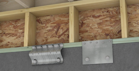
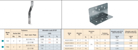
Securing the floor system (rim and end joist) to the cripple wall is also often done incorrectly because the wrong metal hardware is used. Sometimes the metal hardware that is used is foundation anchor ties, which are great at resisting tension forces caused by uplift in hurricanes and strong winds but do a very poor job of resisting shear forces. Certainly, in an earthquake there can be some uplift forces induced from overturning as shown above in Figure 1; however, the majority of the seismic forces are shear forces. The correct hardware for this situation is a shear transfer angle which provides 6 to 14 times as much shear strength (1,340 to 2,900 vs 205 lbs) as a foundation anchor, as shown in Table 1 below.
Bracing the Cripple Wall
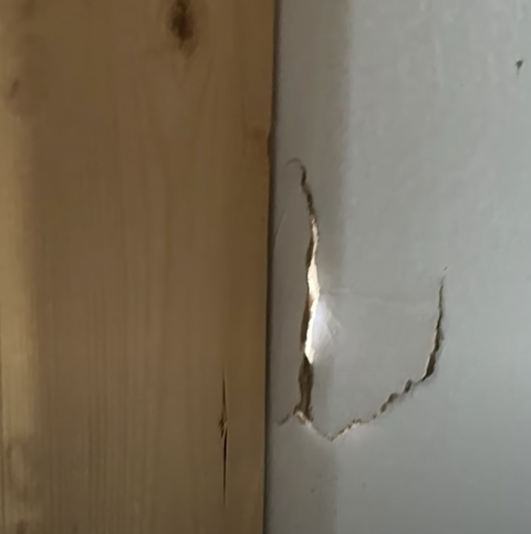
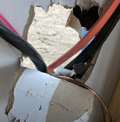
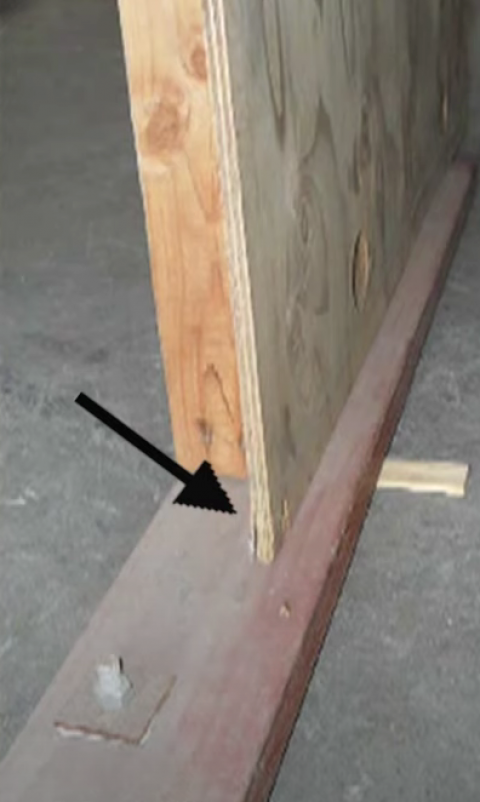
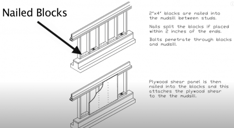
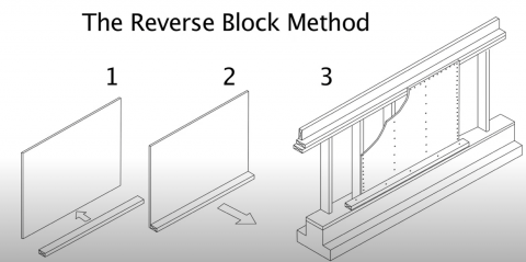
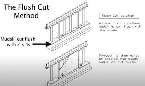
The bracing of the cripple wall can also be done incorrectly. For example, not nailing the sheathing to the mud sill as shown in Figure 3, which results in the cripple wall sheathing providing no appreciable shear bracing strength. One correct way to do this retrofit is to install blocking to the mud sill to provide a nailing surface for the plywood as shown in Figure 4. The blocking is installed onto the mudsill using staples because the number of nails needed would often result in splitting the wood of the blocking or worse, splitting the wood of the mud sill. The second way to do this is to nail the plywood shear paneling to a piece of 2x4 and then nailing the assembly to the cripple wall as shown in Figure 5. The third and most tested method, with thousands of tests done by the APA, is the flush cut method. A flush cut saw cuts the mud sill flush so that plywood can be installed flush with the mud sill as shown in Figure 6.
Retrofit Bracing of the Walls
Walls are trickier and messier to retrofit. This guide talks about the installation of shear bracing. When shear bracing is installed, hold downs should also be installed when the drywall is opened or cut up. Please refer to the guide on Retrofit Bracing of Roofs for Hurricane, High Wind, and Seismic Resistance for more information about load paths and uplift hold downs. This video link showcases many first-floor collapses that are the result of inadequate shear strength in the walls to resist the simulated earthquake loads (Source: Bay Area Retrofit 2020). As demonstrated in the video, it is important to prioritize retrofit bracing of the first floor in a two- or more-story house. The retrofit shear wall installation methods described below address homes with inadequate shear wall strength. This almost always means a home that has no continuous sheathing and was braced with only a few let-in braces that don't meet the current minimum braced wall panel length. Let-in-braced homes are particularly weak, so much so that current building codes don't allow that bracing method to be used in seismic design categories D0, D1, D2. However, a properly implemented let-in-braced home will still perform much better than an old home that is severely inadequately braced and sometimes this is the best option for balancing strength and minimizing the intrusiveness of the retrofit. Homes that have continuous sheathing perform much better against seismic loads and generally don't need additional bracing (Source: Cook 2021).
Method 1 - Retrofit Installing Wood Structural Panels
Wood structural panels (WSP) such as plywood or OSB can be installed in exterior walls with the correct nailing pattern to increase the shear strength of the walls. In new construction, this sheathing is placed on the exterior so that insulation, HVAC, electrical, and plumbing can be easily installed during construction.
However, for retrofit work, it is usually easier to remove the drywall and install the sheathing from the inside than it is to remove the exterior siding and weather-resistant barrier to install WSP to add shear-strength sheathing (McCormick 2002) These panels should cover the full height of the wall such that the WSP can be nailed to the sill plate, studs, and top plate.
The amount and location of WSP to use depends on the home's configuration, which affects the braced wall line length, the number of stories, and the seismic design category. Use the WSP column in Table R602.10.3(3) of the IRC to determine the minimum length of braced wall panels for that braced wall line and at a minimum apply adjustment 8, gypsum board omitted from inside face of braced wall panels, from Table R602.10.3(4) to account for the lack of continuous sheathing with shear strength on the outside face of the wall. Note you still need to distribute the braced wall paneling along a braced wall line so that there is at least one panel within 10 ft of each end of the braced wall line. They should be spaced no more than 20 ft apart as shown in Figure 3 on the Description tab (Figure R602.10.2.2 in the IRC) and fastened every 6 inches on the edges and 12 inches in the field for studs spaced 16 inches on center as indicated in Table R602.3(3) of the IRC.
Because the WSP will cause the wall depth to be out of plane by the thickness of the WSP, constructability dictates that the entire exterior wall of the room being retrofitted be sheathed in WSP and then the drywall replaced. Electrical outlet boxes will need to be shifted outwards to account for the WSP thickness.
Method 2 - Retrofit Installing Let-In-Bracing
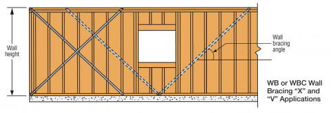
An alternative and less disruptive method for adding shear strength to a wall is to install 1x4 wood let-in-bracings in an X or V configuration as shown in Figure 7 below. For an even less disruptive method, metal wall bracing can be installed instead of the 1x4 wood braces in the same X or V configuration as shown in Figure 7. These metal braces must be installed in pairs because when used singly they can resist tension but not compression forces. One example product is the metal wall bracings from the manufacturer Simpson Strong-Tie, in the WB, WBC, TWB, and RCWB product family. To install this bracing, cut out a strip of drywall the width of the let-in-brace. Use a long ruler or level to help you cut straight. For walls covered with lath and plaster, a track saw with the cut depth limiter adjusted may be used to make the cut. The cut-out strip must go from the top plate to the bottom plate for the brace to be effective. Once the let-in-bracings are installed, the drywall can be patched. Refer to the wind and seismic bracing tables in the IRC, Table R602.10.3(1) and Table R602.10.3(3) for guidelines on how much bracing is needed.
Method 3 - Retrofit Installing an Inset Shear Panels
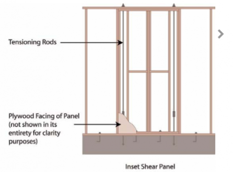
An inset shear panel is a picture frame constructed from dimensional lumber that is made to fit inside a stud bay that is sheathed with plywood or OSB. The panel is then inserted into the stud bay and screwed to the existing studs as shown in Figure 8. In a 2x6 wall, using 2x4 dimensional lumber to construct the shear panel insert allows the whole unit to fit inside the stud bay and not protrude. In a 2x4 wall, the shear panel insert can be constructed using ripped-down 2x4s so that the insert does not protrude from the stud bay.
Commercially available inset shear panels are available that have tested shear strengths for earthquake and high wind loads along with ICC-approved documentation (ICC Evaluation Service 2021). These inset shear panels should be distributed along the braced wall line so that there is at least one within 10 ft of each end of the braced wall line and space them no more than 20 ft apart as shown in Figure 3 on the Description tab (Figure R602.10.2.2 in the IRC). In retrofit applications, the drywall in a stud bay will need to be cut out to make room to install the inset shear panel. Since inset shear panels do not protrude out of the framing plane, drywall can be easily replaced after the retrofit work is complete.
Compliance
There are no unique building codes or regulations for retrofit wall bracing work. Refer to the description tab on wall bracing for guidance on how to navigate the codes regarding current requirements for wall bracing for wind and seismic loads.
Access to some references may require purchase from the publisher. While we continually update our database, links may have changed since posting. Please contact our webmaster if you find broken links.
References and Resources*
*For non-dated media, such as websites, the date listed is the date accessed.
Contributors to this Guide
The following authors and organizations contributed to the content in this Guide.
Mobile Field Kit
The Building America Field Kit allows you to save items to your profile for review or use on-site.
Sign Up or Log In
Did you find this information helpful?
Source: https://basc.pnnl.gov/resource-guides/wall-bracing-hurricane-high-wind-and-seismic-resistance
0 Response to "Different Bracing Methods Are Permitted Within a Continuously Sheathed Braced Wall Line"
Postar um comentário